Reliable feeding
Review surface structure against board, speed and contact pressure.
 JUNSHIDA
For lead edge feeders on corrugated machinery. Match replacement wheels to the original dimensions, hole positions and contact profile.
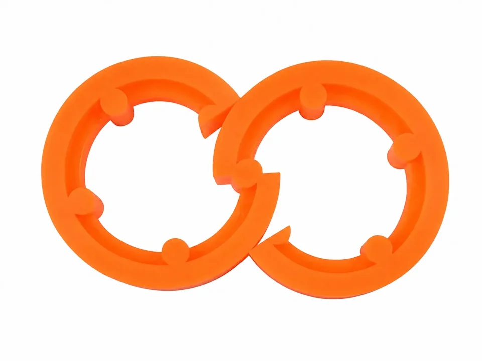
Lead edge feed wheels require consistent friction and dimensions so corrugated sheets start reliably. Wheel size, hole pattern and surface profile must match the original system.
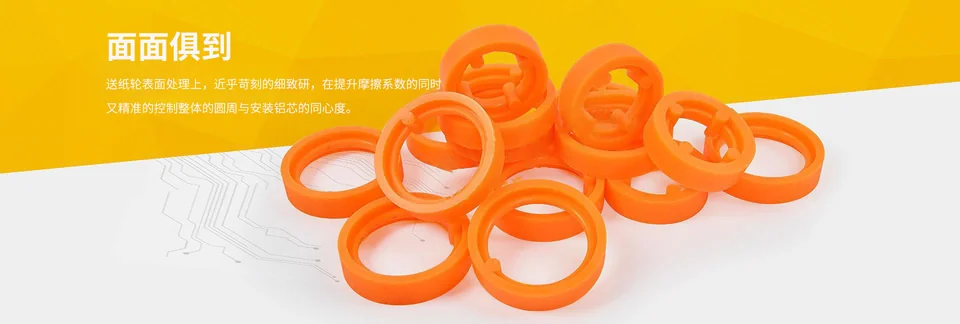
Review surface structure against board, speed and contact pressure.
Confirm center bore, pin holes, screw holes, keyway and hub.
Review a complete old wheel, dimension drawing and machine information.
| Dimensions | Outside diameter, bore, width and hub dimensions |
|---|---|
| Drive interface | Drive holes, pin holes, screw holes, keyway and pitch |
| Surface | Smooth, patterned, slotted or machine-specific profile |
| Application | Machine model, feeding position, board and operating speed |
| Inquiry data | Front/back photographs, dimensions, quantity and symptom description |
Sun wheels provide compliant conveying and guiding; lead edge wheels work in the feeder. Similar appearance does not make them interchangeable.
Confirm bore, bearing, hub, holes, pins and contact profile. Use a physical sample for complex geometry.
Review board type, contact pressure and operating conditions. Colour alone does not identify hardness or material specification.
Measure the maximum diameter and note whether the original wheel is visibly worn.
Record shaft or bearing dimensions, overall width and contact-face width.
Photograph teeth, slots, grooves and openings from the front, side and back.
Confirm hubs, hole counts and spacing; include drive-pin diameter, height and position where fitted.
Provide machine model, position, board type, known hardness and required quantity.
For slipping, marks or skew, include speed, pressure, wear pattern and photographs of the installed set.
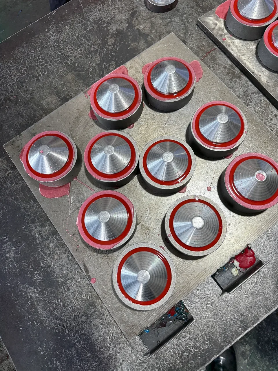
This photograph records the casting stage. Finished diameter, bore, width and mounting geometry are confirmed from the original part, drawing or sample.
Colour does not establish hardness or final specification.
Dimensions, contact profile, bearing or hub details can be reviewed from photographs, a drawing or a sample.
No. Hardness, geometry, contact pressure, wear and diameter consistency across the set must be reviewed together.
Clear measurements and photos may be enough for a simple structure. A sample is recommended for complex profiles or special mounting details.
Trial suitability depends on dimensions, mold requirements and the production schedule.
Share your machine, dimensions and operating conditions.
We’ll help you confirm the material and structure.